


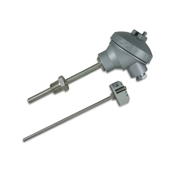
Resistance thermometers, also called resistance temperature detectors (RTDs), are sensors used to measure temperature. Many RTD elements consist of a length of fine wire wrapped around a ceramic or glass core but other constructions are also used. The RTD wire is a pure material, typically platinum, nickel, or copper. The material has an accurate resistance/temperature relationship which is used to provide an indication of temperature. As RTD elements are fragile, they are often housed in protective probes.
RTDs, which have higher accuracy and repeatability, are slowly replacing thermocouples in industrial applications below 600 °C.[1]
#(Resistance/temperature relationship of metals)
Common RTD sensing elements constructed of platinum, copper or nickel have a repeatable resistance versus temperature relationship (R vs T) and operating temperature range. The R vs T relationship is defined as the amount of resistance change of the sensor per degree of temperature change.[1] The relative change in resistance (temperature coefficient of resistance) varies only slightly over the useful range of the sensor.
Platinum was proposed by Sir William Siemens as an element for a resistance temperature detector at the Bakerian lecture in 1871:[2] it is a noble metal and has the most stable resistance–temperature relationship over the largest temperature range. Nickel elements have a limited temperature range because the amount of change in resistance per degree of change in temperature becomes very non-linear at temperatures over 300 °C (572 °F). Copper has a very linear resistance–temperature relationship; however, copper oxidizes at moderate temperatures and cannot be used over 150 °C (302 °F).
The significant characteristic of metals used as resistive elements is the linear approximation of the resistance versus temperature relationship between 0 and 100 °C. This temperature coefficient of resistance is denoted by α and is usually given in units of Ω/(Ω·°C):
{\displaystyle \alpha ={\frac {R_{100}-R_{0}}{100\,{\rm {^{\circ }C}}\cdot R_{0}}},}{\displaystyle \alpha ={\frac {R_{100}-R_{0}}{100\,{\rm {^{\circ }C}}\cdot R_{0}}},}
where
{\displaystyle R_{0}}R_{0} is the resistance of the sensor at 0 °C,
{\displaystyle R_{100}}{\displaystyle R_{100}} is the resistance of the sensor at 100 °C.
Pure platinum has α = 0.003925 Ω/(Ω·°C) in the 0 to 100 °C range and is used in the construction of laboratory-grade RTDs. Conversely, two widely recognized standards for industrial RTDs IEC 60751 and ASTM E-1137 specify α = 0.00385 Ω/(Ω·°C). Before these standards were widely adopted, several different α values were used. It is still possible to find older probes that are made with platinum that have α = 0.003916 Ω/(Ω·°C) and 0.003902 Ω/(Ω·°C).
These different α values for platinum are achieved by doping; basically, carefully introducing impurities into the platinum. The impurities introduced during doping become embedded in the lattice structure of the platinum and result in a different R vs. T curve and hence α value.
#(Calibration Edit)
To characterize the R vs T relationship of any RTD over a temperature range that represents the planned range of use, calibration must be performed at temperatures other than 0 °C and 100 °C. This is necessary to meet calibration requirements. Although RTDs are considered to be linear in operation, it must be proven that they are accurate with regard to the temperatures with which they will actually be used (see details in Comparison calibration option). Two common calibration methods are the fixed-point method and the comparison method.[citation needed]
Fixed point calibration
is used for the highest-accuracy calibrations by national metrology laboratories.[3] It uses the triple point, freezing point or melting point of pure substances such as water, zinc, tin, and argon to generate a known and repeatable temperature. These cells allow the user to reproduce actual conditions of the ITS-90 temperature scale. Fixed-point calibrations provide extremely accurate calibrations (within ±0.001 °C). A common fixed-point calibration method for industrial-grade probes is the ice bath. The equipment is inexpensive, easy to use, and can accommodate several sensors at once. The ice point is designated as a secondary standard because its accuracy is ±0.005 °C (±0.009 °F), compared to ±0.001 °C (±0.0018 °F) for primary fixed points.
Comparison calibrations
is commonly used with secondary SPRTs and industrial RTDs[4]. The thermometers being calibrated are compared to calibrated thermometers by means of a bath whose temperature is uniformly stable. Unlike fixed-point calibrations, comparisons can be made at any temperature between −100 °C and 500 °C (−148 °F to 932 °F). This method might be more cost-effective, since several sensors can be calibrated simultaneously with automated equipment. These electrically heated and well-stirred baths use silicone oils and molten salts as the medium for the various calibration temperatures.
#(Element types Edit)
The three main categories of RTD sensors are thin-film, wire-wound, and coiled elements. While these types are the ones most widely used in industry, other more exotic shapes are used; for example, carbon resistors are used at ultra-low temperatures (−273 °C to −173 °C).[5]
Carbon resistor elements
are cheap and widely used. They have very reproducible results at low temperatures. They are the most reliable form at extremely low temperatures. They generally do not suffer from significant hysteresis or strain gauge effects.
Strain-free elements
use a wire coil minimally supported within a sealed housing filled with an inert gas. These sensors work up to 961.78 °C and are used in the SPRTs that define ITS-90. They consist of platinum wire loosely coiled over a support structure, so the element is free to expand and contract with temperature. They are very susceptible to shock and vibration, as the loops of platinum can sway back and forth, causing deformation.
Thin-film PRT
Thin-film elements
have a sensing element that is formed by depositing a very thin layer of resistive material, normally platinum, on a ceramic substrate (plating). This layer is usually just 10 to 100 ångströms (1 to 10 nanometers) thick.[6] This film is then coated with an epoxy or glass that helps protect the deposited film and also acts as a strain relief for the external lead wires. Disadvantages of this type are that they are not as stable as their wire-wound or coiled counterparts. They also can only be used over a limited temperature range due to the different expansion rates of the substrate and resistive deposited giving a "strain gauge" effect that can be seen in the resistive temperature coefficient. These elements work with temperatures to 300 °C (572 °F) without further packaging, but can operate up to 600 °C (1,112 °F) when suitably encapsulated in glass or ceramic. Special high-temperature RTD elements can be used up to 900 °C (1,652 °F) with the right encapsulation.
Wire-wound PRT
Wire-wound elements
can have greater accuracy, especially for wide temperature ranges. The coil diameter provides a compromise between mechanical stability and allowing expansion of the wire to minimize strain and consequential drift. The sensing wire is wrapped around an insulating mandrel or core. The winding core can be round or flat, but must be an electrical insulator. The coefficient of thermal expansion of the winding core material is matched to the sensing wire to minimize any mechanical strain. This strain on the element wire will result in a thermal measurement error. The sensing wire is connected to a larger wire, usually referred to as the element lead or wire. This wire is selected to be compatible with the sensing wire, so that the combination does not generate an emf that would distort the thermal measurement. These elements work with temperatures to 660 °C.
Coil-element PRT
Coiled elements
have largely replaced wire-wound elements in industry. This design has a wire coil that can expand freely over temperature, held in place by some mechanical support, which lets the coil keep its shape. This “strain free” design allows the sensing wire to expand and contract free of influence from other materials; in this respect it is similar to the SPRT, the primary standard upon which ITS-90 is based, while providing the durability necessary for industrial use. The basis of the sensing element is a small coil of platinum sensing wire. This coil resembles a filament in an incandescent light bulb. The housing or mandrel is a hard fired ceramic oxide tube with equally spaced bores that run transverse to the axes. The coil is inserted in the bores of the mandrel and then packed with a very finely ground ceramic powder. This permits the sensing wire to move, while still remaining in good thermal contact with the process. These elements work with temperatures to 850 °C.
The current international standard that specifies tolerance and the temperature-to-electrical resistance relationship for platinum resistance thermometers (PRTs) is IEC 60751:2008; ASTM E1137 is also used in the United States. By far the most common devices used in industry have a nominal resistance of 100 ohms at 0 °C and are called Pt100 sensors ("Pt" is the symbol for platinum, "100" for the resistance in ohms at 0 °C). It is also possible to get Pt1000 sensors, where 1000 is for the resistance in ohms at 0 °C. The sensitivity of a standard 100 Ω sensor is a nominal 0.385 Ω/°C. RTDs with a sensitivity of 0.375 and 0.392 Ω/°C, as well as a variety of others, are also available.
#(Two-wire configuration Edit)

Two-wire resistance thermometer
The simplest resistance-thermometer configuration uses two wires. It is only used when high accuracy is not required, as the resistance of the connecting wires is added to that of the sensor, leading to errors of measurement. This configuration allows use of 100 meters of cable. This applies equally to balanced bridge and fixed bridge system.
For a balanced bridge usual setting is with R2 = R1, and R3 around the middle of the range of the RTD. So for example, if we are going to measure between 0 and 100 °C (32 and 212 °F), RTD resistance will range from 100 Ω to 138.5 Ω. We would choose R1 = 120 Ω. In that way we get a small measured voltage in the bridge.


 Two-wire resistance thermometer
The simplest resistance-thermometer configuration uses two wires. It is only used when high accuracy is not required, as the resistance of the connecting wires is added to that of the sensor, leading to errors of measurement. This configuration allows use of 100 meters of cable. This applies equally to balanced bridge and fixed bridge system.
For a balanced bridge usual setting is with R2 = R1, and R3 around the middle of the range of the RTD. So for example, if we are going to measure between 0 and 100 °C (32 and 212 °F), RTD resistance will range from 100 Ω to 138.5 Ω. We would choose R1 = 120 Ω. In that way we get a small measured voltage in the bridge.
Two-wire resistance thermometer
The simplest resistance-thermometer configuration uses two wires. It is only used when high accuracy is not required, as the resistance of the connecting wires is added to that of the sensor, leading to errors of measurement. This configuration allows use of 100 meters of cable. This applies equally to balanced bridge and fixed bridge system.
For a balanced bridge usual setting is with R2 = R1, and R3 around the middle of the range of the RTD. So for example, if we are going to measure between 0 and 100 °C (32 and 212 °F), RTD resistance will range from 100 Ω to 138.5 Ω. We would choose R1 = 120 Ω. In that way we get a small measured voltage in the bridge.
Comments
Post a Comment